Back in the 1970s, as USAF aircraft featured increasingly sophisticated communications and electronic warfare systems, the service established a secretive testing project to measure the emissions and effectiveness of aircraft antennae systems. Known unofficially as the “Upside-Down Air Force,” the project is still an important part of USAF testing to this day.
The Upside-Down Air Force has involved many types of aircraft over the years, from fighters to tankers, including the C-130 Hercules featured above, which was pictured in July 1986. At that time, the testing operation was part of the Air Force’s Rome Air Development Center (RADC), attached to the then Griffiss Air Force Base located in Rome, New York.
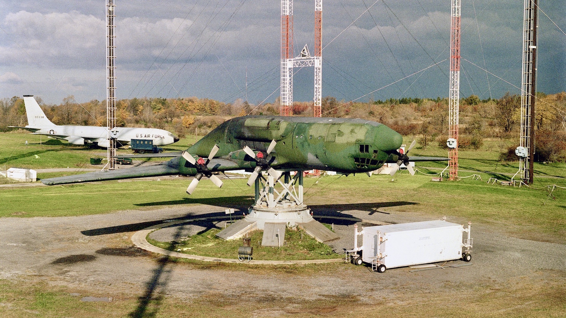
The project involves bolting aircraft to 30-to-50-foot high pedestals. Essentially, this allows the Air Force to perform aircraft underside antenna functionality and emissions tests on the ground, rather than in the air. The latter is both very costly and less capable of delivering detailed data. Doing this work on the ground provides far more control over the positioning of aircraft compared to during flight testing and longer periods can be set aside to test than just when an aircraft is available and airborne. Mapping emissions patters around the aircraft and finding out things like what parts of the jet interfere with signals from different aspects were all part of this kind of testing.

The RADC was inaugurated at Griffiss on June 12, 1951, and was created to lead the development of early warning and command and control equipment for continental air defense under Air Force Systems Command (AFSC). It was not until 1971 however that the Upside-Down Air Force was established by RADC. Three research sites were created for testing under the project around Griffiss; all of which were selected because of the relative isolation of the land and its topography.
At the Verona test site, located roughly 11 miles southwest of the base, the Precision Antenna Measurement System (PAMS) was used from the early 1970s to perform dynamic antenna measurements and evaluate the radiation characteristics of airborne aircraft. This allowed for various sorts of data on the effectiveness of antennas to be collected. Prior to this, antennas would be tested on partial aircraft mockups or scale models. However, as the Air Force noted, “this method has not provided enough realistic data on the antennas and the effect of the aircraft on the antenna characteristics. The development of the Precision Antenna Measurement System (PAMS) was undertaken to provide the type of data that is needed to accurately describe the effective radiation profile of airborne antenna systems.”

According to RADC’s 1973 guide on PAMS, the system provided “the capability to conduct engineering evaluations of airborne antennas designed for use on tactical aircraft equipped with ECM [electronic countermeasures] and associated penetration aids. The facility operates over the frequency range of 0.1 – 18 GHz and is capable of receiving AM, FM, CW or pulse-type signals of any polarization. Measurements are correlated with the aircraft altitude and are conducted on a real-time radiated basis. Types of measurements include power (peak signal amplitude), density (peak signal amplitude X the IF Bandwidth) and integrated (integrated amplitude over octave or increments of an octave bandwidth in terms of DBW/MHZ). The final plotted data can be outputed in polarization, rectangular or three dimension.”
For static testing, on the other hand, aircraft were separated by size. At the Newport test facility, located approximately 18 miles from Griffiss and consisting of several ranges, smaller aircraft testing was conducted, notably involving fighters and attack aircraft. From as early as 1972, RADC initiated efforts to investigate antenna measurement patterns of an ECM pod-equipped F-4 aircraft, for example.

“Originally slated for the salvage heap, RADC mounted the aircraft upside-down on a three axis pedestal at the… Newport Test Site to conduct the tests,” a subsequent official report by the Air Force states. “Antenna coverage by the pod appeared satisfactory with the pod removed from the aircraft, but unacceptable when installed.”
An F-111, F-15, and YF-16 were added in 1976, 1979, and 1980, respectively. Newport also received a YA-10 with the serial number 71-1369, although when that occurred exactly remains unclear.


The Stockbridge research site, located 16 miles southwest of Griffiss, was reserved for static testing with larger aircraft. A B-52 was acquired in 1974, and in 1986 the aforementioned C-130 Hercules arrived at the base.

Positioning aircraft upside-down for antenna testing had distinct benefits for the Air Force. As Richard Rabe, whose career was spent mainly studying the effects of electromagnetic energy on antenna capability at the RADC’s Electromagnetic Compatibility Analysis Facility (EMCAF) noted previously, placing aircraft upright on pedestals would ruin tests due to the pedestals themselves getting in the way.
“The way to solve that problem was totally placing the aircraft upside-down. With antennae on the belly of the plane and the belly facing the sky, we could rotate, tip and spin the plane any way we wanted and the pedestal would be safely below the aircraft and out of the way.”

In terms of the broader benefits for the Air Force, Dr. Michael Hayduk, deputy director of the Information Directorate, Air Force Research Laboratory (AFRL/RI), has noted in the past that the RADC’s approach to RF measurement “has saved the Air Force countless hours and dollars over traditional flight testing, which is exemplary in our success in prioritizing time, cost and efficiency in the Air Force.”
With regard to testing of the YF-16, Gregory Zagar of the AFRL’s RI has said previously that, owing to the fact that the aircraft could be mounted in various positions and be exposed to testing from different spots around the test site due to the nature of the landscape, “a single ten-minute rotation of the airframe at Newport resulted in more antenna pattern data than that collected in one hour of flight test time, at significantly lower cost, and risk.”

Collecting antenna pattern data in this manner has been important for the Air Force because the physical appearance of aircraft, even of the same type, can drastically differ based on specific stores configurations. As such, the placement of fuel tanks, missiles, bombs, dispensers, and pods in different combinations all have an impact on the effectiveness of aircraft antennae systems.
Both RADC and Griffiss underwent changes into the 1990s, but this did not stop antenna and RF system testing. In 1991, RADC was re-named the Rome Laboratory, constituting one of the Air Force’s four ‘super-laboratories’ — the others being the Armstrong Laboratory in Texas, the Phillips Laboratory in New Mexico, and the Wright Laboratory in Ohio. The Rome Laboratory specializes in command, control, and communications research and development, and is now home to the aforementioned AFRL/RI; the Air Force’s premier research organization for Command, Control, Communications, Computers, and Intelligence (C4I) and Cyber technologies.

In 1995, Griffiss AFB was closed as part of the Base Realignment and Closure (BRAC) process, and is now home to the Griffiss Business and Technology Park. However, the off-base Rome Laboratory was retained, alongside the Eastern Air Defense Sector (EADS) of the North American Aerospace Defense Command (NORAD).
Since then, the Upside-Down Air Force has continued to be used for testing out new electronic warfare capabilities, while newer aircraft have also been added. In 2014, for example, a full-scale F-35C model was turned upside-down and mounted on a pedestal at the Newport test site in order to measure antenna patterns.

It should be noted that the Upside-Down Air Force is just one part of a vast infrastructure that the Department of Defense has created for electromagnetic testing of various vehicle types, which you can read more about in these past War Zone pieces. In addition, beyond emissions, radar cross section testing also frequently involves aircraft being bolted to pedestals, and often upside down in a similar fashion to the those seen above.
So if you happen to be walking through the countryside of central New York state, there’s a good chance you could end up seeing some of the Air Force’s upside-down aircraft, which have played an important role there for over half a century.
Contact the author: oliver@thewarzone.com